Engineering results
you can measure.
Explore how our UAV LiDAR and photogrammetry workflows helped engineering teams deliver accurate, design-ready data faster across utility corridors, infrastructure projects, and statewide mapping programs.
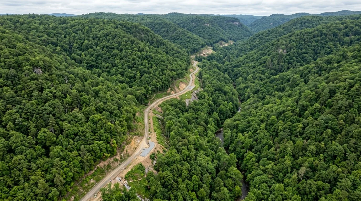
Regional sewer corridor, dense tree canopy
01. Challenge
Sky Shot supported engineering design for a major regional wastewater infrastructure alignment spanning several miles of challenging terrain, where over 50% of the corridor was obscured by dense tree canopy.
Conducting traditional ground surveying alone over this corridor would have required months of labor-intensive brush cutting, difficult site access coordination, and elevated field safety risks.
02. Method
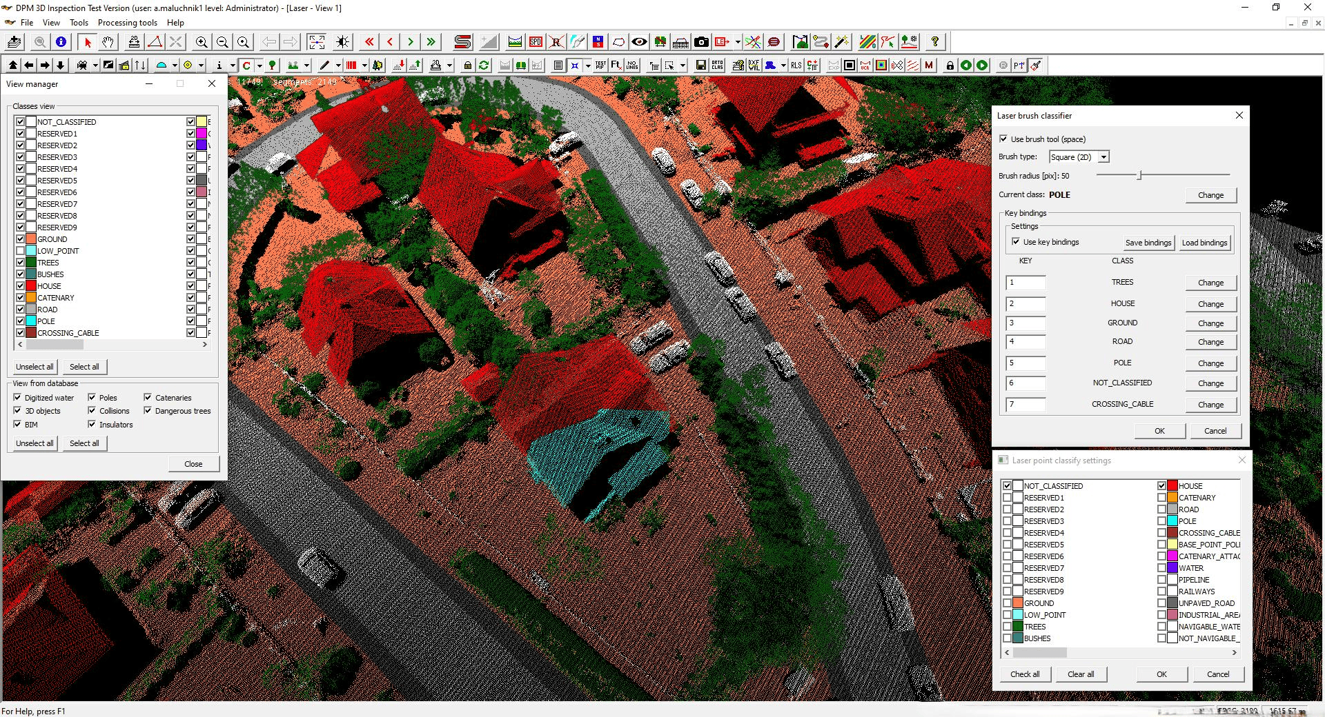
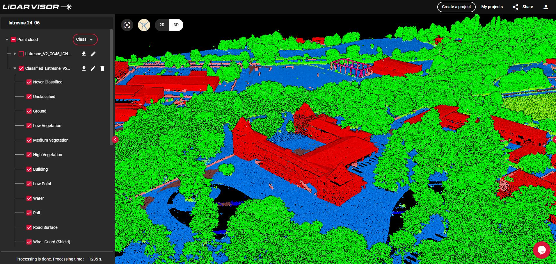
To optimize data collection, Sky Shot deployed high-density aerial UAV LiDAR integrated with aerial photogrammetry. The airborne LiDAR sensor penetrated the vegetation canopy to model bare-earth ground elevations, while high-resolution imagery captured surface features.
 SURFACE: DENSE FOREST CANOPY
 LIDAR: CLASSIFIED BARE-EARTH DEM
QA/QC & Accuracy Methodology
Aerial data collection was calibrated against a network of ground control points (GCPs) and independent check points surveyed via Real-Time Kinematic (RTK) GNSS. Bare-earth point cloud classifications were cross-verified through field sampling to validate vertical and horizontal tolerances prior to CAD export.
03. Deliverables
The project delivered engineering-grade geospatial assets fully referenced to the local project coordinate system:
04. Results
By combining UAV LiDAR acquisition with ground control verification, the engineering team received complete, design-ready deliverables in 2 weeks instead of the estimated 3–5 months for ground-only methods.
Project Delivery Timeline Comparison
88% TIME SAVED- Delivered final engineering mapping within 14 calendar days
- Achieved verified ±0.10 ft vertical and ±0.15 ft horizontal accuracy
- Significantly reduced field exposure and crew safety risks in dense brush
200+ acre utility infrastructure program

01. Challenge
An extensive water and wastewater utility renewal program spanning over 200 acres required existing condition mapping across steep terrain and long corridors.
Decades-old legacy infrastructure had surface appurtenances—valves, meters, manholes, and sample stations—scattered across residential easements and hard-to-access properties, requiring rapid asset inventorying without schedule delays.
02. Method
Sky Shot executed systematic UAV aerial mapping to capture ultra-high-resolution orthophotography and surface elevation data. Photogrammetric point clouds were processed to identify and extract visible surface utility assets.
 AERIAL ORTHO SURFACE
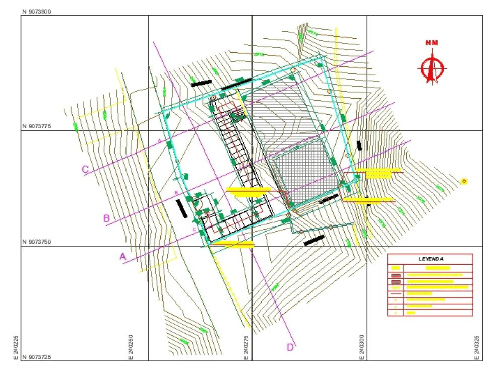
 CIVIL 3D VECTORIZED BLOCKS
QA/QC & Accuracy Methodology
Extracted asset locations were cross-referenced against utility field observations and legacy system maps. Positional accuracy was verified using RTK-surveyed ground control points, ensuring asset coordinates aligned with project CAD standards.
03. Deliverables
The design team received a comprehensive suite of digital utility assets:
04. Results
The integrated UAV aerial survey delivered complete engineering-ready assets in just over 1 week, drastically accelerating preliminary utility conflict analysis and design drafting.
Turnaround Acceleration
7-DAY TURNAROUND- Consolidated months of asset documentation into a 7-day turnaround
- Mapped hundreds of utility appurtenances into Civil 3D blocks
- Streamlined preliminary design for municipal utility upgrades
Multi-site water facility assessment program

01. Challenge
A regional infrastructure improvement program required preliminary engineering assessments across 18 water treatment facilities distributed over a wide geographic area.
Legacy site documentation was incomplete or outdated. Engineers needed rapid, standardized existing-condition data for each plant—including tanks, chemical systems, structures, access roads, and operational boundaries—before initiating design.
02. Method
Sky Shot established a standardized UAV aerial mapping and site documentation workflow across all 18 facility locations. Aerial imagery was captured at low altitudes to maximize surface detail for plant equipment and structural footprints.
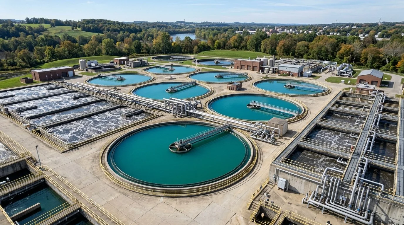 PLANT AERIAL ASSET VIEW
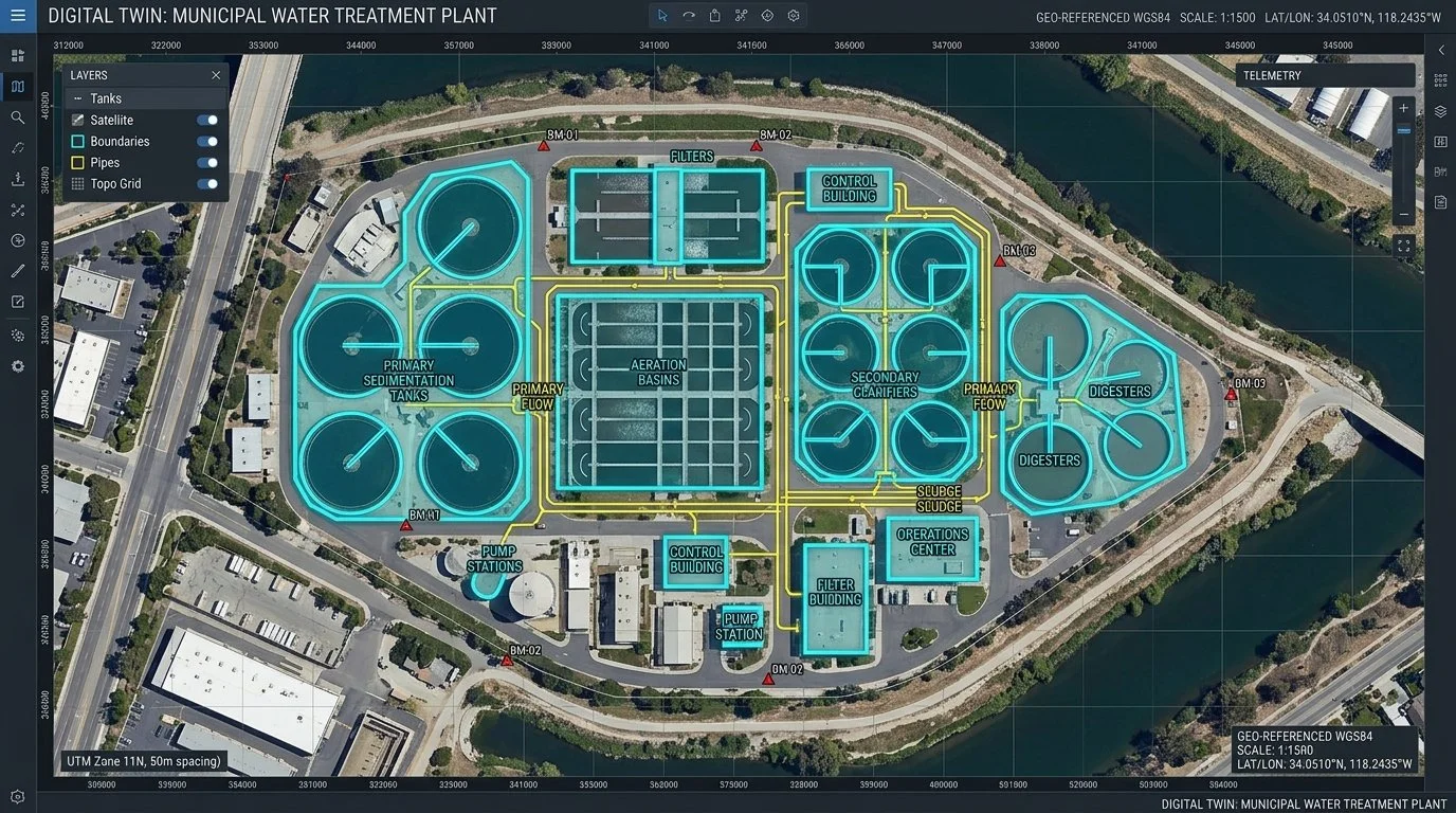 DIGITAL TWIN BASELINE
QA/QC & Accuracy Methodology
Each facility survey incorporated ground-verified checkpoints and regulatory record cross-referencing. Geospatial data across all 18 sites were unified under a single QA/QC protocol to guarantee consistent CAD layer structures and coordinate positioning.
03. Deliverables
A standardized, multi-site engineering package was provided for the entire program:
04. Results
In approximately 1 week, the engineering team received complete, standardized site packages for all 18 facilities, eliminating weeks of preliminary site visits and drafting delays.
Multi-Site Program Velocity
18 SITES IN 7 DAYS- Delivered 18 standardized plant site packages within 7 business days
- Provided immediate design-ready CAD basemaps for program engineers
- Established a verified digital baseline for multi-facility upgrades
What a delivered
surface looks like
Classified LiDAR point cloud surfaces exported into Civil 3D — ready to sample, contour, and design against.